|
#1
 09-11-2005, 03:48 PM
|
|||
|
|||
|
I'm still trying to figure out exactly how to do this. The microscope *I* used isn't very good and only went to 40x. I had to take pictures by holding my digital camera to the eye piece. At the university we have a metallurgy microscope with a hard mounted camera. I might try to look with that one too.
This is the sample image the decapping company sent me: 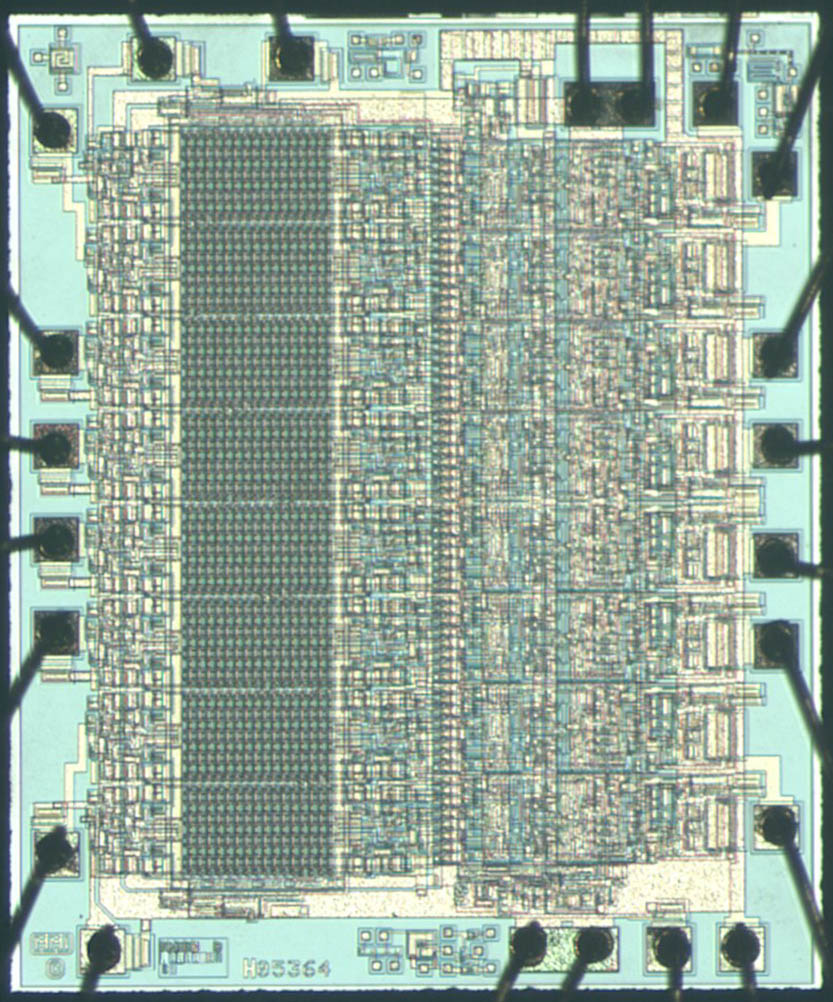 I was surprized how bad this next picture was. I was told by MEFAS that the image below was taken with a "stereo microscope". He said to get the image he got, use an "optical microscope". There is a metallurgy microscope at UAA that I will use to finish the project. 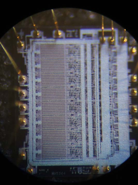 That's what I was able to get with the work microscope and a digital camera held up to the eye piece. Each block of the PAL should resemble this: 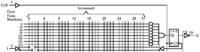
Last edited by Grant Stockly; 09-12-2005 at 07:41 PM. 
|
|
#2
09-12-2005, 07:47 PM
|
|||
|
|||
|
Here is the image I got at UAA. Its not the best, but its pretty good considering I was holding a cheap digital camera to the eye piece.
 Taken at 50x. Taken at 50x.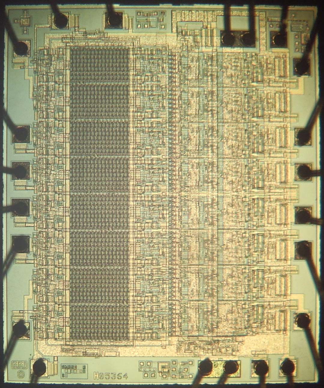 Here is the HAL chip that we're taking pictues of. The little white thing is the silicon block above. The rectangle bar pointed to by the arrow is the fuse map. 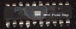 Here is a chip-art picture for fun. 96x mag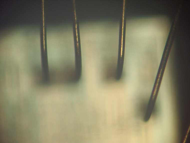 Here is the MMI logo at 200x. All the pictures below are at 200x. That circular thing is a wire landing pod. 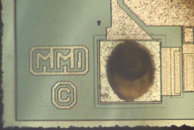 Here is the fusemap with text indicating where the pin inputs are and the flip flop result outputs. There are 256 fuse positions in that field. 8x32. Taken at 200x. 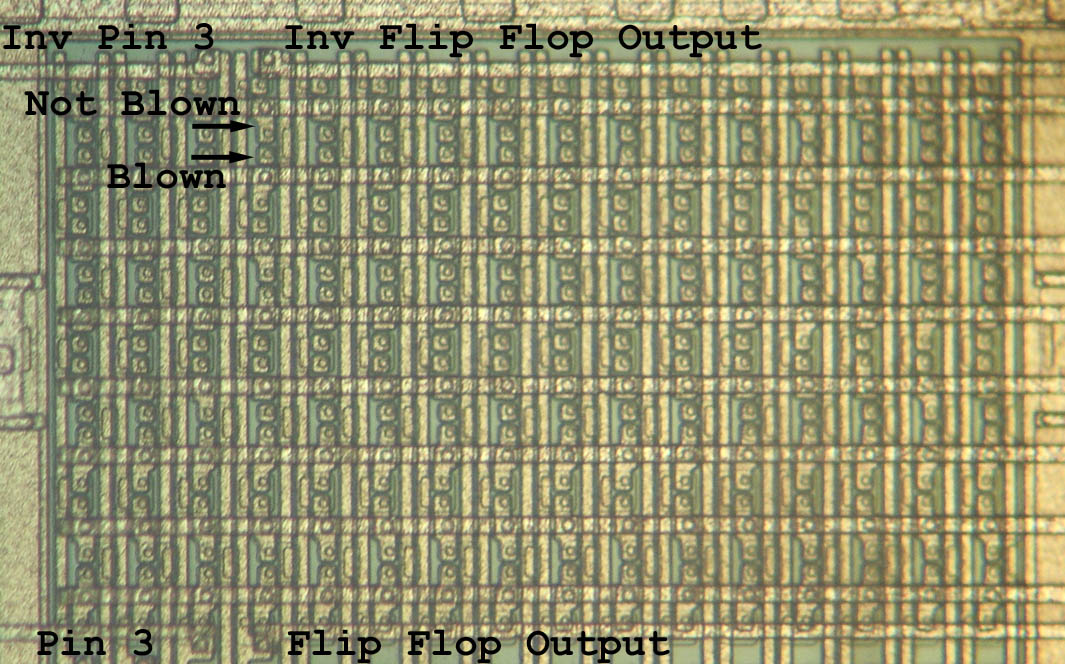 Here is just to the right of the fusemap, just for fun. 200x 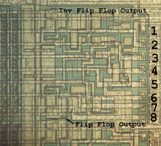
|
|
#3
09-16-2005, 12:43 PM
|
|||
|
|||
|
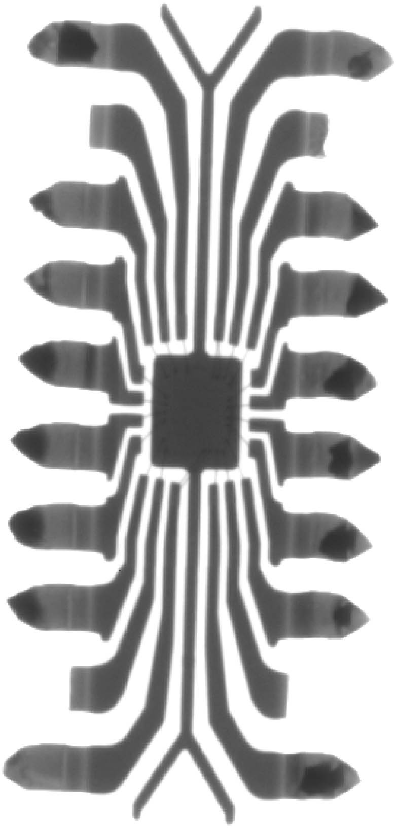
Here is an X-Ray of the package showing the bond wires connections.
|
|
#4
09-17-2005, 04:55 PM
|
|||
|
|||
|
Here is the fusemap for the ASG PAL. Starting with pin 2 and going to pin 10. (blocks 1 through 8) The right hand side of the pictures are blury because the right side of the camera lens had to be spaced further from the eyepiece than the left to fit the whole image. I plan to build an adaptor for my camera so that it takes higher quality images.
Here is a high resolution version. 1.7mb, 20.4 mega pixels! 091705-ASG-fuseblock-pano-fullres-cropped.jpg And here is the "low resolution version": 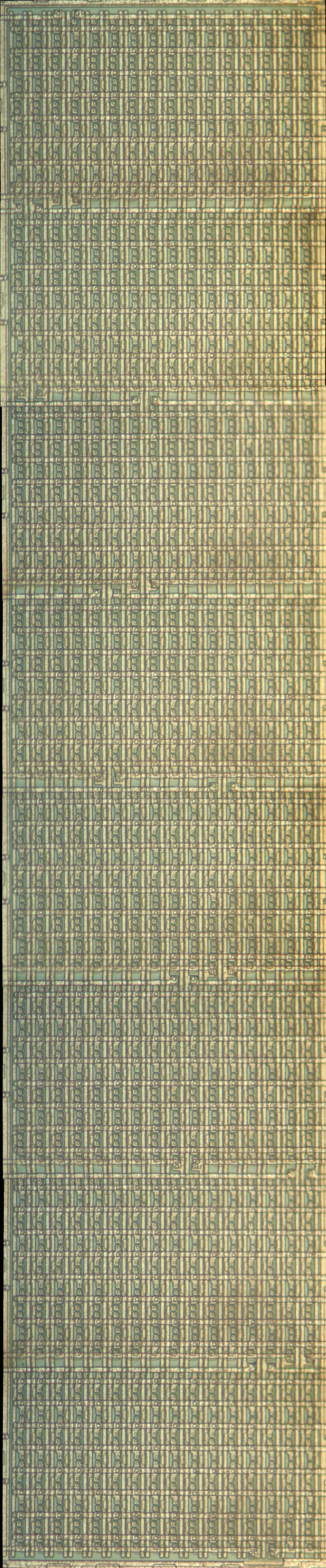
|
 |
|
|
 Similar Threads
|
||||
| Thread | Thread Starter | Forum | Replies | Last Post |
| QX5 microscope | tonigau | Electronics | 0 | 02-05-2006 05:09 PM |
| Microscope examination of a PLD | Grant Stockly | Electronics | 7 | 09-05-2005 02:56 PM |


 Linear Mode

