|
|
|
#1
 09-08-2007, 09:50 PM
|
|||
|
|||
|
I'm working onthe 2SIO board and trying to figure out how to wire the molex connector to the 25 DB female connector. I cannot figure out how to match up the pins. In the MITS manual I have, it is supposedly described on pages 28 and 29.
Page 28 describes the molex connector. It refers to pins 1, 2, 3, 4, 7, 8, and 10. I'm guessing that page 29 describes the 25 DB connector (it is not labeled). It refers to pins 2, 3, 4, 3, 8, 20, and 7 The problem is that page 28 shows 2 grounds while page 29 shows only 1, and page 29 shows a DTR on pin 20 and page 28 has no corresponding pin. Any ideas? Paul 
|
|
#2
09-09-2007, 01:33 AM
|
|||
|
|||
|
Hi Paul;
I did this awhile back, and ran into the same problem  Here is what I did, and I got it to work with my PC. Since I am not at my place and am out of town for another week or so. I can only tell you what I did remotely, and with a bad memory, mine , not the computers. I assume for now that you are using your PC with Hyperterminal. Here is what I did, and I got it to work with my PC. Since I am not at my place and am out of town for another week or so. I can only tell you what I did remotely, and with a bad memory, mine , not the computers. I assume for now that you are using your PC with Hyperterminal.I looked up rs-232 on the WEB, and looked for 9 pin to 25 pin, and used modem half duplex one way and full duplex the other. The full duplex is from the Altair to the Pc and the half duplex is the other way. Since the 2Sio Board doesn't provide a full duplex both ways. I should be something like this -- I am doing this from memory, so I might be wrong. connect the following -- 2 (on the 25 pin) to 3 (on a 25 pin) or its equivalent on the 9 pin 3 "" to 2 "" "" 7 "" to 7 "" "" (and I think the following) 4,5,8 "" to 20 "" "" 20 "" to 4,5,8 "" "" ( I know pins 4 or 5 possibly may not be right) and on the Pc to the Altair side as you said it doesn't have 'DSR' So it can't be connected. If you need more help, I can look it up on the web and tell you almost for sure which ones to use. Or wait until I get back home and I will see what my machine has wired up. Thanks Marty 
|
|
#3
09-09-2007, 02:37 AM
|
|||
|
|||
|
Thanks Marty, but I think you answered the question that I would have asked pretty soon. I think you are describing the wiring between the 25 pin connector on the Altair and the 25 or 9 pin connector on my PC. Yep, that would have been a question I would have had to ask.
 But I'm a step before that. I'm trying to figure out the wiring inside the Altair case, between the 10 pin Molex connector that attaches to the 2SIO board and the 25 pin connector that I am going to mount on the back of the Altair case. Give your explanation of what happens outside the case, I may be able to figure out the wiring inside the case. But please do look, when you get home, at that part of the wiring inside the case and let me know what you did there. I’d appreciate it. It seems that you keep bailing me out, Marty. I sure appreciate it!  I hope to return the favors some day. I hope to return the favors some day.Paul
|
|
#4
09-09-2007, 06:44 AM
|
|||
|
|||
|
Hi Paul;
You are right about the manual pages. I had to Download it to this computer, ( I have all of these files on my machine at home and my download to this machine came by a slow boat through China.) so yes -- pin 1 on the sio board to pin 5 of the rs-232 2 " 8 " 3 " 4 " ( and 20, I think) 4 or 10 " 7 " 7 " 2 " 8 " 3 " 10 or 4 " 7 " What I did to first try it out and make sure I was right ,, was to use wirewrap wire and just wrap the wire onto the 2-sio board connection and soldered it to the rs-232 connection on the other side to make sure it works. Before pinning the wire on the 2-sio side. Then bring up Hyperterminal and see IF it works, if not then make modifications. (by slipping wires on and off of the pins on the 2-sio) Hyperterminal will let you know when it is happy with the connection. THANKS Marty 
|
|
#5
09-09-2007, 08:51 PM
|
|||
|
|||
|
Hey Paul. I took notes when I wired mine. Here are the notes with pictures of my card below.
I THINK I wired both of my ports for RS-232 hardware handshake but did not connect the hardware handshake wires for port 0 that would keep the card from working without hardware handshaking. Basically, the hardware handshaking is disabled with an easy way of adding it in the future. You should be able to use the pictures of the DB25 connector on one end and the molex on the other to figure out how I wired it. The ribbon cable is junk.  Basic Tx/Rx/Gnd Serial Configuration: D3 to I4 - Port 0 Receive I3 to S1-7 - Port 0 Receive D5 to N4 - Port 0 Transmit N3 to S1-8 - Port 0 Transmit S1-4 to S1-10 - Port 0 Ground E3 to J1 - Port 1 Receive J2 to S2-7 - Port 1 Receive E5 to N6 - Port 1 Transmit N5 to S2-8 - Port 1 Transmit S2-4 to S2-10 - Port 1 Ground Hardware Handshake: D2 to I7 - Port 0 Clear to Send (D2 end NOT connected) I8 to S1-1 - Port 0 Clear to Send D1 to I5 - Port 0 Data Carrier Detect (D1 end NOT connected) I6 to S1-2 - Port 0 Data Carrier Detect D4 to N2 - Port 0 Request to Send N1 to S1-3 - Port 0 Request to Send E2 to I2 - Port 1 Clear to Send I1 to S2-1 - Port 1 Clear to Send E1 to J3 - Port 1 Data Carrier Detect J4 to S2-2 - Port 1 Data Carrier Detect E4 to N8 - Port 1 Request to Send N7 to S2-3 - Port 1 Request to Send These are big pictures, so hopefully no one with a modem will try to load the page. 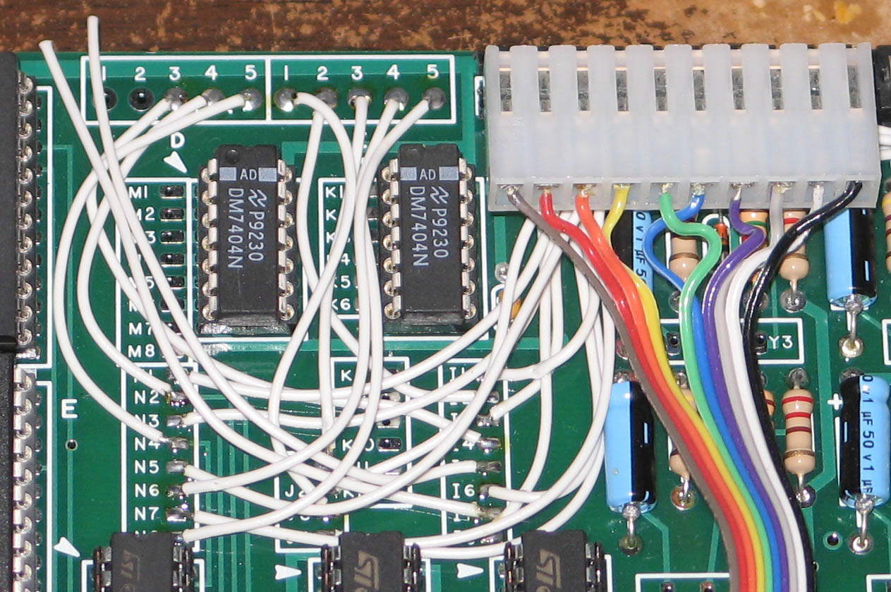 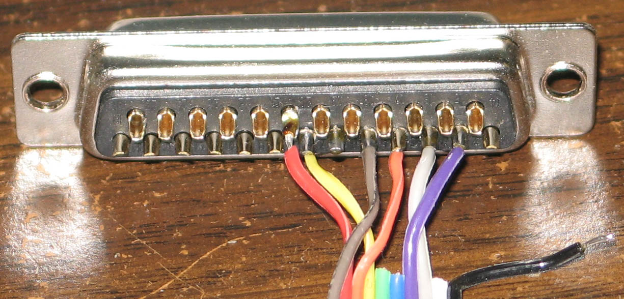 
|
|
#7
09-13-2007, 02:26 AM
|
|||
|
|||
|
Any updates Paul?
Grant
|
|
#8
09-27-2007, 02:57 AM
|
|||
|
|||
|
Well, after a long time away from the hobby due to extensive priorities at work, I'm back at it again. The diagram you posted, Grant, was extremely helpful. I have the board all wired and "almost" all the ICs in. There are two ICs that are a mystery, and rather than try hit/miss I figured I'd ask here first.
In the MITS intructions, page 3, IC G is defined as a 93L34 and IC F is simply defined as a 16 pin socket. Lovely. In the kit I have two ICs left over. One is marked GD4702B and the other is marked 74LS259. Any idea whic is G and which is F? I'd like to get this board working! Once I install the last two IC's, what's the best way to test? Is there a preferred loader program, or otherwise, that I enter in via the switches that will at least display something on the RS-232 terminal? Thanks guys. Paul
|
|
#9
09-27-2007, 04:35 AM
|
|||
|
|||
|
Do you remember the e-mail I sent you on 7/20 with the 600 DPI scan of my card! ; )
The GD4702B chip is the chip called "4702". The 74LS259 is a LS TTL version of the 93L34. Here is a link to a scan of the complete card. Its a pretty big picture! http://www.stockly.com/images3/090720-88-2SIO%20Replica%20Prototype%20Top.jpg
|
|
#10
09-30-2007, 12:01 AM
|
|||
|
|||
|
From the book:
Echo routine for the Altair 8800 computer to communicate with a serial terminal via the 88-2SIO. Page 140 of "The S-100 Bus Handbook". 000 : 076 001 : 003 002 : 323 003 : 020 004 : 076 005 : 021 006 : 323 007 : 020 010 : 333 011 : 020 012 : 017 013 : 322 014 : 010 015 : 000 016 : 333 017 : 021 020 : 323 021 : 021 022 : 303 023 : 010 024 : 000
|
 |
|
|
 Similar Threads
|
||||
| Thread | Thread Starter | Forum | Replies | Last Post |
| Help needed wiring display board to expansion board | phe | Altair 8800 | 8 | 04-03-2007 01:07 AM |


 Hybrid Mode
